In the master’s courses on Control Systems at the Eindhoven University of Technology, we learn about amazing techniques for feedback and feedforward control.
However, we’re usually given a ready-to-use Matlab/Simulink environment, set up on an ancient real-time Linux kernel with EtherCAT, achieving sample rates of 2-4 kHz. I wanted to play around with control systems at home and such a setup was too expensive, slow, and cumbersome for my liking.
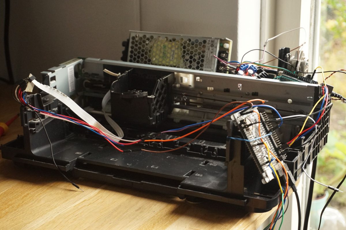
So instead, I decided to set up a hard real-time platform for less than €10 worth of hardware, capable of reaching at least 8 kHz sample rates. The application: closed-loop control of an old A4 consumer printer. The main goal is to implement Iterative Learning Control (ILC) on this printer, and possibly LQG and direct data-driven control.
In this blog, I’ll write updates on my progress. The audience I’m writing for is people who have a decent understanding of control systems, but want to learn more about the (low-cost) application to real systems. For those unfamiliar with control systems, this paper is a great place to start. My own specialization is Learning Control, and I’m a beginner in electronics and embedded systems. Expect cool control techniques and poor soldering jobs. I appreciate any feedback in the comments, especially about embedded systems and electronics.

This blog series will be structured as follows:
- Part 1: Requirements, Preferences and Constraints. Here, I’ll outline the exact specifications I set at the start.
- Part 2: Hardware selection, in which I compare several options and explain why I ended up buying these specific parts.
- Part 3: Initial design of the real-time platform. In this part, I describe how I achieve a hard real-time control loop and how the printer communicates with my computer without loss of samples.
- Part 4: Modeling and controller design. I’ll perform a Frequency Response Function (FRF) measurement and fit a transfer function. A feedback controller is designed in this part too.
- Part 5: Implementation of Iterative Learning Control, and comparison of the performance with basic feedforward.
- Part 6: On implementation aspects of control, where I explain what I learned about the practical side of control engineering.
A sneak preview of the results:

Don’t hesitate to leave comments if you have questions/suggestions or if you learned something, I’m happy to respond! Start reading here.

I’m a Dutch PhD candidate at the Control Systems Technology group of TU/e.
You will want to put inductors between the bridge driver and the motor, unless the motor coils (3-phase?) have ‘sufficient’ inductance already (or unless you can raise the switching frequency high enough without increasing losses). The difference between the square-wave bridge voltage and the motor back-EMF is across the coils and controls the time-derivative of the current (not the current itself).
Dear Marcel,
Thanks for the advice, I appreciate it! It’s a 2-phase DC motor, I’ll look into this. From this, I conclude that increasing the inductance will move one pole of the voltage->angle transfer function to s=0. In that case the motor has 2 integrators and an extra pole. I’m currently looking into whether this is what I want, or whether I should look for circuits that allow me to set the current directly with PWM (i.e., only two integrators). Since most of my control courses assume torque as input, and basis functions feedforward generally assumes this too, that would be an attractive setup.
The reference you cite gives a motor model that is fine for simple control purposes. With the square wave bridge switching far above the sample frequency, one can assume that the motor is driven with a (independent) current source instead of a voltage. Effectively this makes di/dt = 0 and a very simple first order system results.
When the ratio of switching frequency and sample rate drops, at some point the control of bridge and motor start seriously interacting and a more precise model is needed. At that point some power electronics specific knowledge becomes necessary.
Dear Marcel,
your comment “The difference between the square-wave bridge voltage and the motor back-EMF is across the coils and controls the time-derivative of the current (not the current itself).” triggers my question: Isn’t it that the difference between the applied (bridge) and the induced (back EMF) voltages determines the current directly? Well, through a “natural” first-order low-pass filter 1/(Ls+R). The trouble for low inductance motors is then that the smoothing effect of that 1/(Ls+R) is not significant for switching frequencies around 20 kHz (which is typically the case with commercial drivers) as it constitutes just Ohm’s law (converting voltage to current) and the resulting current and hence torque pretty much inherit the square-wave character of the bridge voltage. Designing a digital current controller is then tricky (which samples of the square-wave current to take?).
Could you, please, elaborate a bit more on the “interaction between the control of the bridge and the motor”? Indeed, finding relevant advices and tips in the literature is very difficult.
I/we have been facing this every now and then in projects as the low-cost and low-power DC motors with permanent magnets that we currently use in the projects have very low L. Besides adding an inductance, as you mention, we typically solve it by designing our own drivers with faster switching frequencies (above some 100 kHz) if smoothness of the generated torque (or force) is required in an application.
We have also been experimenting with some current control schemes in which the time instances of switching are directly determined (some elaboration on saturation control), but this brings in the EMC issues that electronics guys hate – the frequencies of the generated noise are absolutely unpredictable.