Introductory post: link
Previous post: link
With the requirements, preferences and constraints defined, let’s choose the hardware.
Microcontroller
Let’s start with the most common choices that people make for hobby projects: Arduino or Raspberry Pi. Neither of these are suitable here. Arduinos have at most PWM frequencies of 1000 Hz and 12 bit resolution, which is far lower than the 16 kHz I required in the previous post. Raspberry Pi might have the required specs, I’m not too sure, but it costs much more than the budgeted €10 and would involve setting up a real-time kernel. For these two reasons I’m crossing the Pi off the list too.

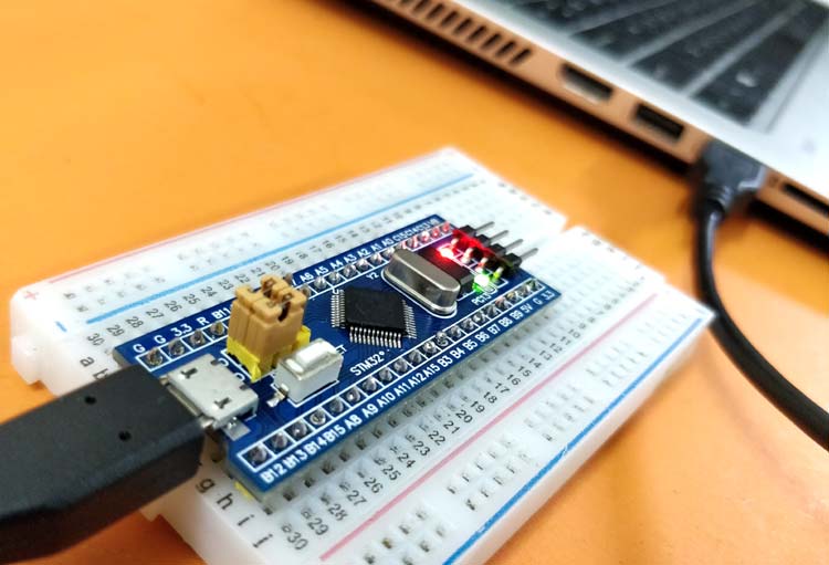
Instead, I started looking into STM32 devices. First I considered the STM32F103C8, which seems to be very popular. It has a 16 bit timer running at 72 MHz, so it’s capable of achieving the PWM rate. It features 2 SPIs with 18 Mbit/s and allows full-speed USB 2.0, which is supposed to reach 480 Mbit/s, much more than the 256 kBit/s I need. It’s dirt cheap too, at about €1. It looks like it could definitely do the job.

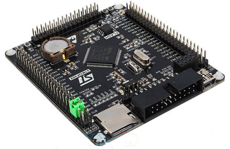
The thing is, I’m not entirely sure yet how many clock cycles my control loop will require. At 8 kHz, this 72Mhz clock can run 9000 cycles per iteration. That’s surely enough for a simple PID loop, but if I want to leave room for LQG or other more advanced techniques, spending €7 more for the beefier STM32F407VET6 might save me some headache down the road. I was recommended this particular board by Enzo Evers, who is working on similar projects, check out his work here.
This microcontroller comes with a bunch more timers too, supports virtual COM ports (which is supposed to be more convenient than regular serial, from what I’ve heard) and features a 168 MHz clock (and consequently, either a higher PWM frequency or higher resolution, which is nice too). Oh, and it has an SD card slot. It’s great value, speaking from my experience with it since the start of the project.
To flash my code to the microcontroller, I use an ST-Link v2. You can get a clone for around €1.50. It’s an USB-stick with pins that connect to the corresponding pins of the microcontroller, see this guide for how to wire it up.
Warning: depending on where you got your ST-Link, the pins might be wired differently. I’d go with the pin order written on the device. For me, this was different than the order of the guide I was using, and it took me way too long to figure that out.

Motor control hardware

With the most important choice out of the way, that just leaves us the hardware for the motor control. At the moment, I decided to go for the L298N H-bridge, a popular DC motor driver that supports 24V and 1 A.
The thing is, if PWM (so, voltage) is the input to the printer, the input is not proportional to torque, which scales with current. Most systems I’ve worked with in my studies have current as input, I still need to look into if I want this, why, and if yes, how. That’s scheduled for part 4; I’ll update this post if I end up buying something extra. Any tips are welcome in the comments.
So for now, the last thing that remains is a 24V power supply. I ended up buying a Mean Well LRS-150-24.
Auxiliary parts
For the next part, setting up the real-time platform, I’ve found it very useful to toggle GPIO pins and read them out with a logic analyzer. I ended up buying this one for €5. And of course, I got a whole load of different cables.
In the next post, I’ll explain how the real-time control loop is set up.

I’m a Dutch PhD candidate at the Control Systems Technology group of TU/e.
