Introductory post: link
Previous post: link
With all the hardware selected, let’s start working on obtaining a real-time control loop. I’ll first describe how I set up the software, then go into how I configured the STM32 board and how to communicate with it, and lastly I’ll verify that everything is working as it should.
Preliminaries: software
STM32 microcontrollers can be conveniently configured using STM32CubeMX. You can install it from here. In this program you can easily configure the role of the pins and clocks, and it spits out a convenient code template for your IDE of choice. For the IDE, in which you write and compile C code and flash the program via the ST-link to the STM32, I chose Keil MDK-Arm, found here. To use the ST-Link v2, you’ll need this driver. You can update the filmware of the ST-Link using this utility program.
Some STM32 devices ship with an stm32duino bootloader, such that you can program it in the Arduino IDE. I did not want this, since I figured it would offer less control of the hardware timers and corresponding registers (but maybe it’s possible that way too). To get rid of it, you can erase the stm32 device via the ST-Link utility mentioned earlier.
STM32 board configuration
Once you’ve installed all these programs, open STM32CubeMX and start a new project. Select your STM32 board, in my case STM32F407VET6. You’ll be greeted with this screen:
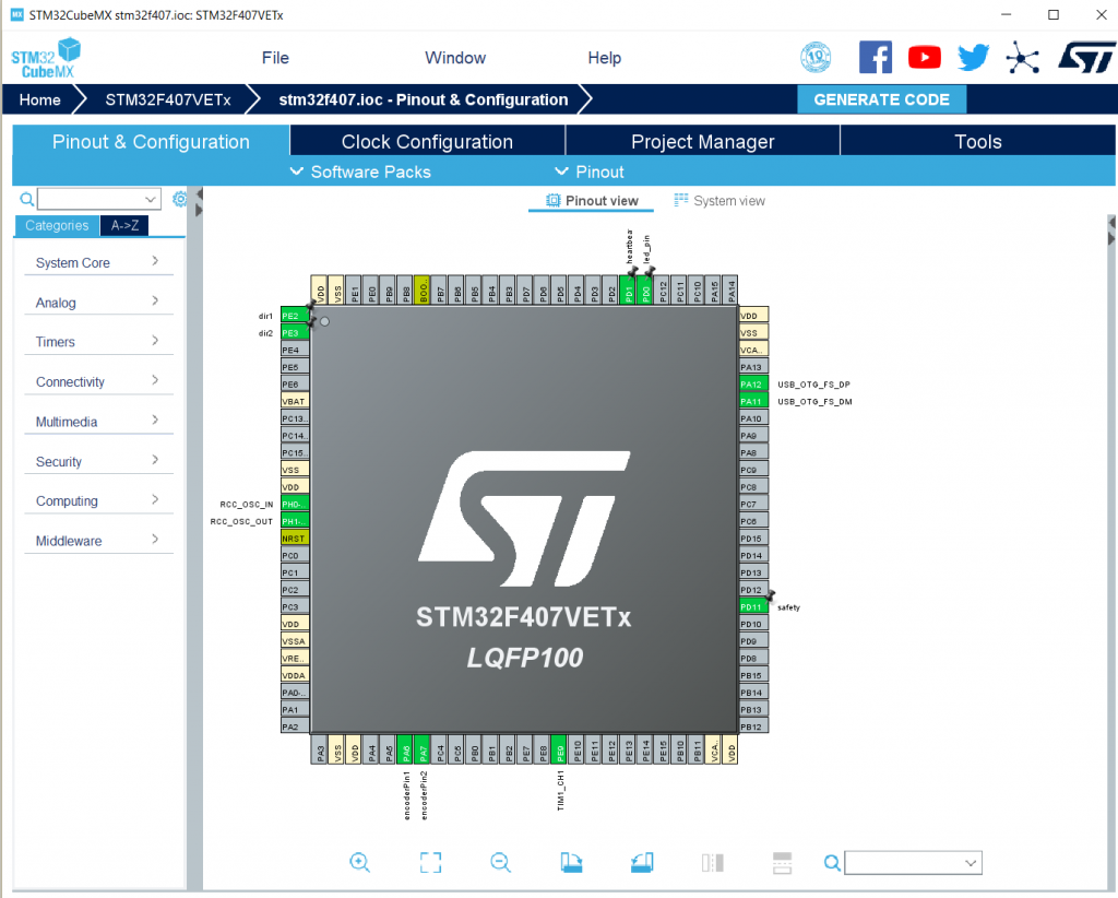
except that I already configured some pins, and yours will be grey without label.
Timer configuration
Let’s start with the most important parts: the timers. One to drive the real-time loop, one to generate a PWM signal and one to keep the encoder count.
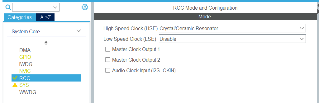
First, click “System Core” in the left tab and click RCC. Make sure the High Speed Clock (HSE) is set to the Crystal/Ceramic Resonator:
Then, we need to choose which timer to assign to which task. An overview of the timers is found in the datasheet:
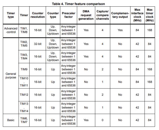
Before moving on, let’s get into more detail about how to interpret these numbers. When configuring a timer, we can set the timer period T_clock, i.e., the number of counts that the timer will do until it will reset. This is at most 2^resolution in the third column. It will count with the frequency f_clock of the rightmost column.
So the frequency at which the timer resets is f_timer = f_clock / T_clock.
Timer for real-time loop
The timer driving the real-time loop needs to trigger an interrupt at at least 8 kHz, the counter resolution is not directly relevant here. Let’s pick TIM2 for this. Since it runs at 84 MHz, let’s choose a timer period T_clock = 2^13 (not that we’re limited to powers of 2, but I prefer this). This is leads to a sample frequency of 84e6 / 2^13 = 10.25 kHz, a little more than we need. In the Timers -> TIM2 menu in the sidebar, enter this:
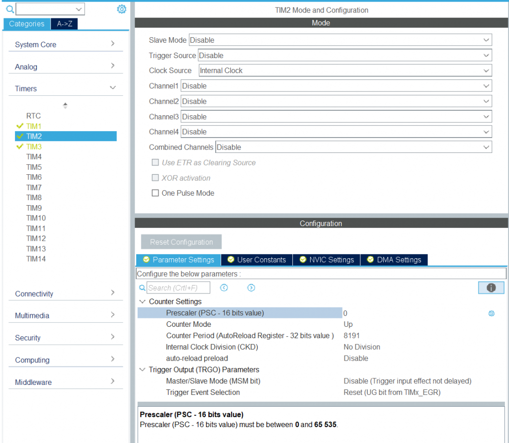
Note that it takes T_clock - 1 = 8191. In the NVIC Settings tab, check the box so that it triggers a TIM2 Global Interrupt whenever the timer resets.
PWM timer
As mentioned in the previous post, the PWM timer is the most critical one. A higher counter resolution allows us a finer range of voltages we can apply, and the clock frequency needs to be over twice the sample frequency. For this reason, let’s pick TIM1 for the PWM timer.
If you’re PWM frequency is in the human hearing range, you can actually hear it squeaking while it’s running. While originally I set the requirement that the PWM frequency must be 2 times the sample frequency, I now doubled it to 41 kHz to get rid of the ~21 kHz sound. Since TIM1 runs at 168 MHz, this corresponds to a timer with a period of 2^12, since 168e6 / 2^12 = 41 kHz. This is exactly the minimum required resolution set in Part 1.
To configure this timer, go to TIM1 in the sidebar of STM32CubeMX and select the following options:
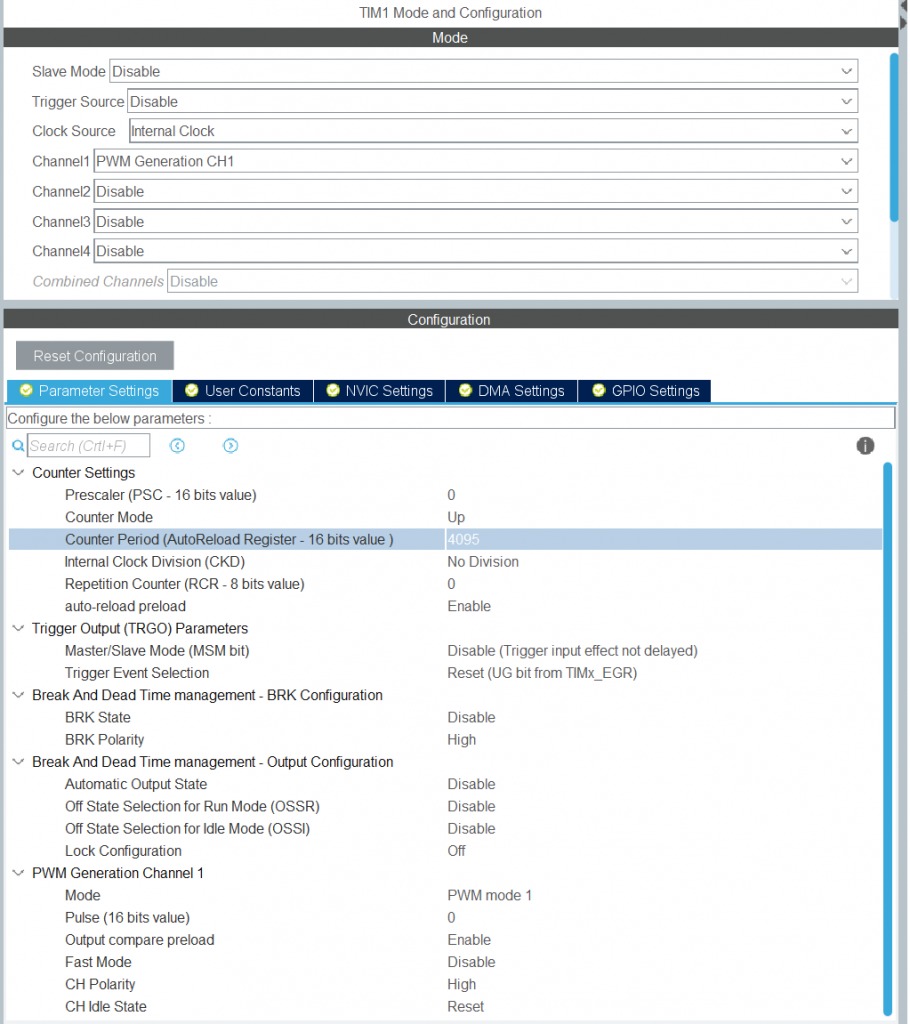
See this for more info on PWM on STM32 microcontrollers.
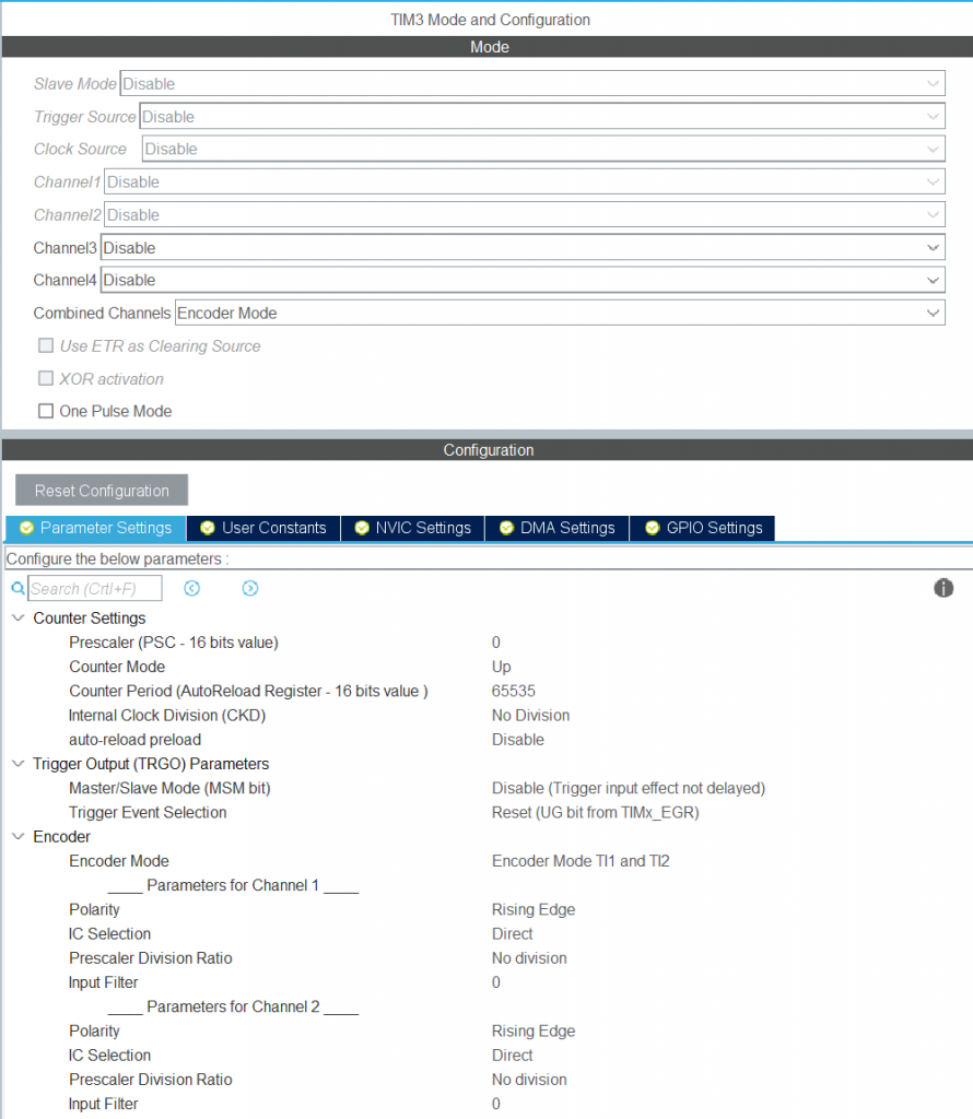
Encoder timer
The photo-interruptor can be interpreted as an encoder and set up by following this guide. I use TIM3 for it. The only difference is that I don’t use an input filter (haven’t read up on what it does, but I’ve been keeping it at 0 and it works fine. Want to keep things as simple as possible). Since our strip has about 8000 slits, a 16-bit resolution is sufficient, so we enter 2^16-1 for the timer period:
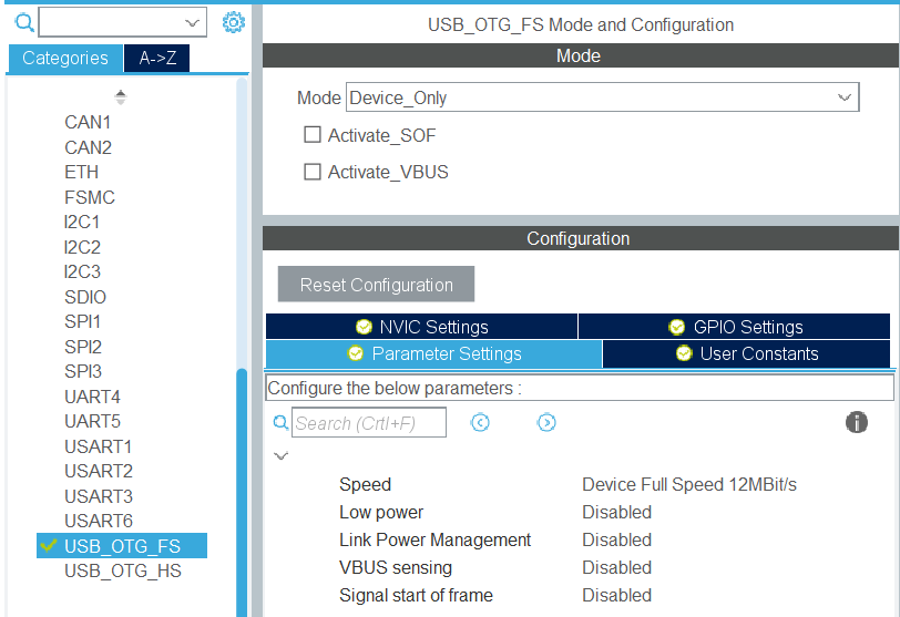
USB configuration
We’ll communicate with the STM32 over USB using a Virtual COM port. I’m not sure what guide I used at the time, but this one seems similar (but on the STM32F407VET6 you can use the on-board USB port). Go to Connectivity -> USB_OTG_FS and select the following:
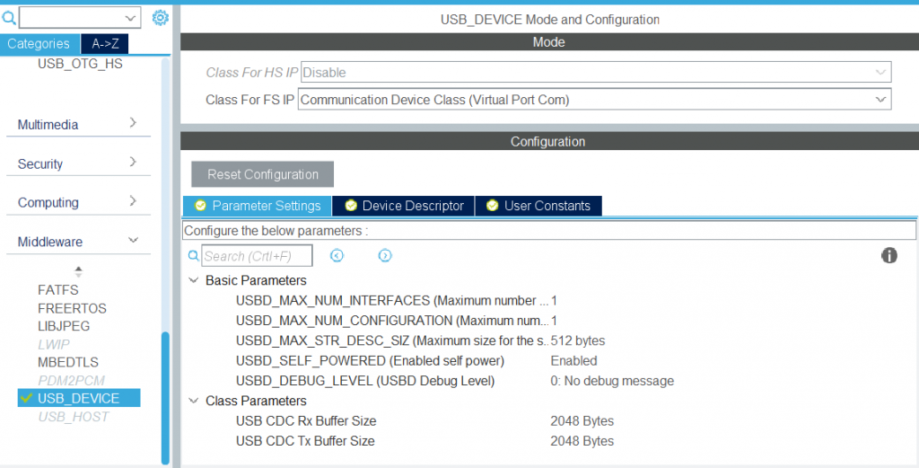
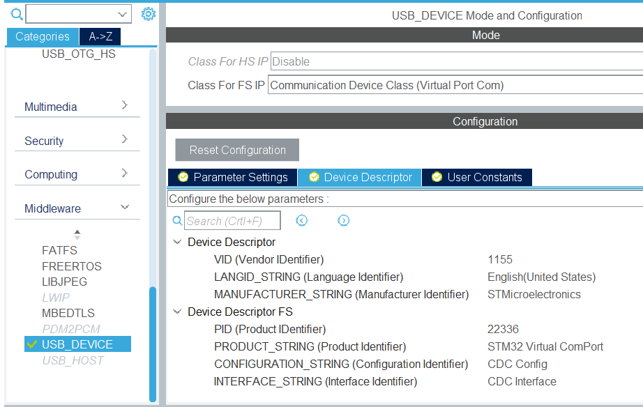
Also select Middleware -> USB_DEVICE:
GPIO configuration
Some pins will be assigned functions automatically based on the settings we’ve configured. However, by right clicking a pin on the STM32 microcontroller image on the right, you can select GPIO_Output and assign it a label. Do this for 2 pins such that we can control the direction of the DC motor, and one more so we can output a ‘heartbeat’ pulse every time we enter the control loop.
Writing the code
In the Project Manager tab on top, select MDK-ARM for the toolchain / IDE and then click Generate Code on the top right. Open the generated .uvprojx in Keil to find the template code.
Code for the real-time loop
In the template, some parts will be managed by CubeMX if you regenerate the code, and some parts are left to be programmed by the user. The latter parts are marked by “USER CODE BEGIN …” and “USER CODE END …”.
I’ll describe next how to set up the bare basics for the real-time loop. If enough people are interested, I’ll consider cleaning up my full code and sharing it on Github.
In “USER CODE BEGIN Includes”, include the following libraries:
#include "usbd_cdc_if.h"
#include <stdlib.h>
#include <stdbool.h>
In “USER CODE BEGIN PV” (private variables):
extern volatile bool flag;
This flag will be set by the interrupt handler. The main loop will execute when this flag is set, and then reset the flag. In “USER CODE BEGIN 1”, inside the main() function:
// Send N samples over USB per buffer
int N = 100;
// Number of bytes sent per sample
int len = 4;
// Initialize the buffer
uint8_t buf[len*N];
// Initialize the iteration counter for USB
int iter = 0;
int16_t encoderPos = 0;
// Set the maximum PWM value at 65% for testing
uint16_t max_pwm = 4096 * 0.65;
uint16_t u;
In “USER CODE BEGIN 2”, to start the timers:
HAL_TIM_Base_Start_IT(&htim2);
HAL_TIM_Encoder_Start(&htim3,TIM_CHANNEL_ALL);
HAL_TIM_PWM_Start(&htim1, TIM_CHANNEL_1);
In “USER CODE BEGIN 3”, inside the while(1) loop:
if (flag) {
    //Make sure an interrupt doesn't interfere with setting the variable
    __disable_irq();
    flag = 0;
    __enable_irq();

    HAL_GPIO_WritePin(heartbeat_GPIO_Port,heartbeat_Pin,1);
    encoderPos = (int16_t) TIM3->CNT;

    u = max_pwm; // For testing
    //Set the motor direction
    HAL_GPIO_WritePin(dir1_GPIO_Port,dir1_Pin,1);
    HAL_GPIO_WritePin(dir2_GPIO_Port,dir2_Pin,0);

    // Copy the encoder position and input voltage to the buffer
    memcpy(&buf[iter*len], (uint8_t *) &encoderPos, sizeof(int16_t));
    memcpy(&buf[iter*len+2], (uint8_t *) &u, sizeof(int16_t));

    if (iter==N-1) {
        iter = -1; // reset iter

        // Send the buffer over USB
        CDC_Transmit_FS(buf,len*N);
    }

    iter++;
    HAL_GPIO_WritePin(heartbeat_GPIO_Port,heartbeat_Pin,0);
}
Lastly, to let the interrupt of TIM2 set the flag, add this function to “USER CODE BEGIN 4”:
void HAL_TIM_PeriodElapsedCallback(TIM_HandleTypeDef *htim) {
	if (flag) {
		HAL_GPIO_TogglePin(led_pin_GPIO_Port,led_pin_Pin);
	}
	flag = true;
}
The LED now functions as a simple overrun detector.
With the code set up, you can compile the code in Keil with F7 and flash it to the board with F8. When it’s done downloading, don’t forget to press the reset button on the STM32 board to run the code.
Communication
To read the messages coming from the STM32, I use realterm. In the PORT tab, select the a sufficient Baud rate (921600 bits/s is more than enough for 2 int16_t variables at 10.25 kHz) and in the Port tab, select the virtual COM port of your device. For me, it’s “9 = \USBSER000”. Open the port and go to the Display tab to select int16. To record a measurement to a file for analysis, just enter a path in the Capture tab and press Start.
Validation
If we analyze the heartbeat pin and the PWM signal with the logic analyzer, we get:
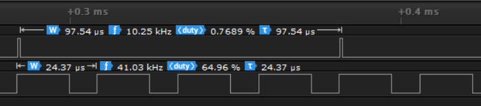
As expected, we have 4 PWM cycles in one sample, and the sample frequency is 10.25 kHz, which is correct. Let’s take a closer look at the recorded heartbeat signals.
If we plot the difference between timestamps when the heartbeat signal becomes HIGH (let’s call this diff(tauvec)), we get a vector of all recorded sample frequencies. Plotted against time, this becomes:
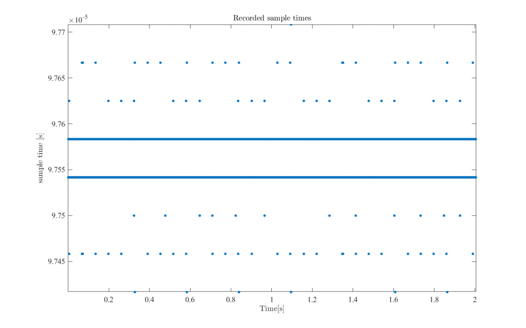
Note that the desired sample time is 9.752 * 10-5 seconds, about 0.04% lower than the average measurement, but the difference is constant, so I’m fine with this. Next, notice that the recorded sample times are spaced with equal distance. Here is a histogram of diff(tauvec):

The two peaks at +-41.6667 ns must be the resolution of my logic analyzer. If the real sample time is not an exact multiple of the resolution, it will regularly snap to the next resolution step. This would also explain the regular pattern in the blue plot above.
For these reasons, I’m willing to call this control loop hard real-time, and assume that the sample time is constant at all time. Of course, as I expand the code executed inside the control loop, I will monitor the overrun detection.
If there are any questions, or if you disagree with any claim, feel free to let me know in the comments. I hope it’s at least useful to someone trying to set up their project 🙂
In the next post, I describe how I did an FRF measurement of the printer and designed a simple controller.

I’m a Dutch PhD candidate at the Control Systems Technology group of TU/e.
Interesting project! Really nice to follow this end-to-end development project. The development of the electronics and embedded software has always been more or less a ‘black box’ during my studies.
You write “I’ll describe next how to set up the bare basics for the real-time loop. If enough people are interested, I’ll consider cleaning up my full code and sharing it on Github.” YES, would be very interesting.
Hi Max,
Very interesting project indeed! Would appreciate it if you could share the code on Github. I’m trying to recreate the microcontroller setup but I’m having issues with some of the timers. Would be good to be able to compare!
Regards,
Berend